Views: 0 Author: Site Editor Publish Time: 2026-09-25 Origin: Site


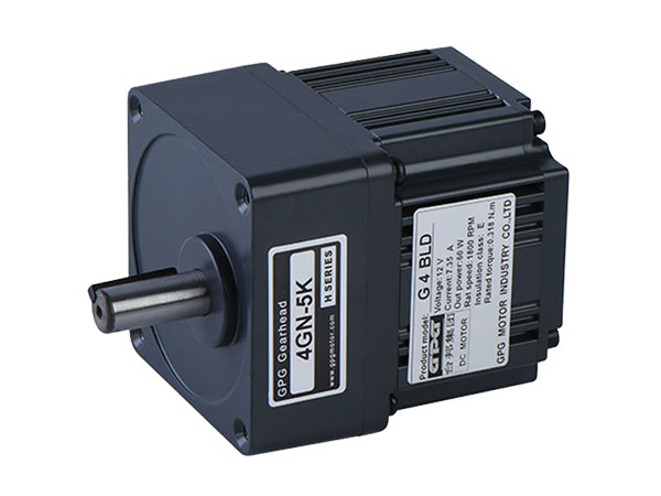
The structural framework of an AC gear motor consists of an electromagnetic AC drive unit integrated directly with a mechanical reduction gearbox. Key internal components include a laminated steel stator, copper wire windings, a squirrel-cage rotor, precision helical or spur gears, heavy-duty support bearings, output shafts, and high-temperature dual-lip oil seals.
Core Electrical Stator Architecture
Precision Rotor and Shaft Integration
Gearbox Reduction Train Mechanics
Bearings, Seals, and Housing Enclosures
Structural Design Variations and Mounting Options
Engineering Maintenance and Operating Protocols
The core electrical stator architecture of an AC Gear Motor serves as the stationary electromagnetic component that converts AC electrical energy into a rotating magnetic field.
The stator is the foundational power center of the electrical drive portion in an AC Gear Motor. It is meticulously assembled using thin, insulated sheets of high-permeability silicon steel laminations stacked together under high pressure. This laminated structure is specifically engineered to minimize eddy current losses and hysteresis heat, which directly impacts overall system efficiency. Embedded within the internal slots of the stator core are high-purity copper magnet wire windings, insulated by multi-layer class H or class F dielectric materials. When alternating current flows through these phase windings, it establishes a uniformly rotating magnetic field that drives the internal rotor without physical contact.
From an industrial design standpoint, the exterior housing surrounding the stator core plays a dual structural role: providing rigid alignment for internal components and acting as a thermal radiator. In heavy-duty conveyor systems and continuous automated production lines, heat build-up is the leading cause of insulation degradation. Our engineering evaluations reveal that European automation clients strongly prefer die-cast aluminum housing alloys with extruded radial cooling fins for medium-duty units, while heavy industrial sectors demand rugged gray cast iron enclosures. Why do we design our stator housings with dual-pattern mounting flanges and integrated terminal boxes? Because real-world factory floors present unpredictable installation constraints, and modular wiring access significantly reduces installation time.
When specifying a drive system for automated material handling equipment, engineers frequently evaluate complete vertical gear motor units to optimize vertical space constraints and achieve direct-drive mechanical efficiency without external belt alignment issues.
Component | Material Specification | Structural Function | Performance Metric |
|---|---|---|---|
Stator Core Laminations | Cold-Rolled Non-Oriented Silicon Steel (0.35mm - 0.5mm) | Directs magnetic flux; reduces eddy currents | Permeability > 1.5 T |
Stator Windings | 200°C Enamelled Copper Magnet Wire | Conducts AC phase current to form rotating field | Dielectric Strength > 2.5 kV |
Insulation System | Nomex / Mylar Slot Liners (Class F / H) | Prevents phase-to-phase and phase-to-ground shorts | Thermal Resistance up to 180°C |
Motor Frame Housing | Die-Cast A380 Aluminum or GG20 Cast Iron | Maintains bearing concentricity; dissipates heat | Heat Dissipation > 120 W/mK |
The rotor and shaft assembly of an AC Gear Motor is the central rotating element that turns electromagnetic forces into smooth mechanical rotation.
Inside the stator bore lies the squirrel-cage rotor, constructed from stacked steel laminations injected with high-purity molten aluminum or copper conductor bars connected by heavy end-rings. As the stator’s rotating magnetic field passes through these rotor bars, it induces an electrical current, generating a opposing secondary magnetic field that forces the rotor to spin. The rotor is mounted on a high-tensile alloy steel shaft precision-ground to micrometer tolerances. The driving end of this rotor shaft extends directly into the gearbox housing, often featuring an integrated or press-fitted helical pinion gear that serves as the input driver for the reduction gear train.
To survive decades of continuous high-speed rotation, the entire rotor and shaft assembly undergoes rigorous dynamic balancing in accordance with ISO 1940 Grade G2.5 standards. Unbalance in the high-speed rotor stage generates high-frequency vibrations that propagate directly into the gear teeth, accelerating pitting and leading to premature bearing fatigue. Why do our advanced drive designs utilize an integral pinion cut directly onto the rotor shaft rather than a separate keyed coupling? Cutting the primary pinion gear directly onto the motor shaft eliminates rotational backlash, reduces cumulative runout, and creates an exceptionally compact footprint that clients in high-speed sorting facilities demand.
During continuous operation, axial and radial mechanical forces generated by the gear mesh are transferred through the rotor shaft to high-precision deep-groove ball bearings seated within machined end-shields. This rigid mechanical support ensures that the motor maintains a perfectly uniform air gap between the stator and rotor, preventing internal rubbing, electrical imbalance, and unexpected mechanical binding under heavy load conditions.
The gearbox reduction train mechanics of an AC Gear Motor utilize precisely meshed gear sets to systematically decrease rotational speed while proportionally increasing output torque.
The gearbox stage is where raw electrical speed is converted into high-torque mechanical power. Depending on application demands, an AC Gear Motor employs spur, helical, bevel, or planetary gear sets. Helical gear designs are overwhelmingly favored in modern industrial applications due to their angled teeth, which engage gradually across the tooth profile rather than all at once. This progressive meshing contact delivers significantly smoother power transmission, higher load-carrying capacity, and dramatically lower acoustic noise levels compared to straight spur gearing.
Inside a multi-stage reduction gearbox, the high-speed input pinion meshes with a larger intermediate gear, which drives a secondary pinion connected to the main output gear. Each gear ratio step multiplies torque while reducing RPM according to exact mathematical ratios. To ensure maximum gear longevity under severe shock loads, gear teeth undergo specialized surface hardening treatments such as carburizing, induction hardening, and precision gear grinding (ISO Grade 6 accuracy).
When machinery builders design specialized lifting or material-elevating machinery, they frequently specify specialized helical flange-mounted gear motors to handle massive overhung loads while maintaining structural rigidity across continuous operation cycles.
Gear Train Type | Contact Ratio | Noise Level (dB) | Mechanical Efficiency | Primary Industrial Application |
|---|---|---|---|---|
Spur Gearing | 1.2 - 1.4 | 78 - 85 dBA | 95% - 97% per stage | Basic low-cost, intermittent duty equipment |
Helical Gearing | 2.0 - 2.5 | 62 - 70 dBA | 97% - 98% per stage | High-speed continuous conveyors & automation |
Planetary Gearing | Multi-tooth contact | 68 - 75 dBA | 94% - 96% overall | High torque density in compact spaces |
Worm Gearing | Line sliding contact | 55 - 65 dBA | 60% - 85% overall | Self-locking right-angle drives |
Gear Tooth Profile Optimization Note: Modern high-efficiency gearboxes utilize a customized crowned tooth profile (longitudinal modification). This intentional micro-geometry adjustment compensates for minor shaft deflection under full load, preventing stress concentration on the tooth edges and increasing total gear fatigue life by up to 45%.
Bearings, seals, and housing enclosures form the protective and structural skeleton of an AC Gear Motor, holding moving parts in alignment and guarding against contaminants.

The structural integrity of an AC Gear Motor relies entirely on its mechanical support architecture. Precision ball and roller bearings support the rotor shaft, intermediate gear shafts, and output shaft. The output shaft bearings face the most demanding environment, as they must simultaneously withstand heavy radial forces from chain sprockets or belt pulleys and axial thrust loads from helical gear geometry. Premium gear motors use heavy-duty tapered roller bearings or reinforced spherical roller bearings on the output stage to prevent shaft deflection and housing distortion.
Surrounding the entire mechanical assembly is a high-strength housing enclosure, typically rated from IP55 to IP66 for dust and liquid protection. To keep gear lubricant inside while excluding water, dust, and abrasive particulates, multi-lip synthetic rubber seals (typically Viton or NBR) are installed at every shaft extension. These oil seals feature spring-loaded primary lips that run on precision-ground, hardened shaft journals, creating a tight micro-fluid barrier.
Why do European factory operators consistently favor synthetic polyglycol (PAG) or synthetic hydrocarbon (PAO) lubricants over standard mineral oils in sealed gear housings? Synthetic gear lubricants provide an exceptionally stable viscosity index across broad temperature ranges (-30°C to +90°C), drastically lower internal fluid friction, and extend oil drain intervals from 2,500 hours up to 10,000 operational hours.
Structural design variations and mounting options determine how an AC Gear Motor integrates physically and mechanically into industrial machinery layouts.
Engineers select gear motor layouts based on available space, shaft orientation requirements, and load characteristics. The three primary mechanical configurations are parallel shaft, right-angle, and inline vertical structures. Parallel shaft designs position the motor rotor parallel to the driven output shaft, offering excellent mechanical efficiency and straightforward mounting for inline conveyor drives. Right-angle configurations utilize worm or bevel gear sets, allowing the motor to sit perpendicular to the driven equipment to save lateral aisle space in tight packaging facilities.
Inline vertical designs are engineered specifically for applications requiring a top-mounted or bottom-mounted vertical drive orientation, such as chemical agitators, fluid mixers, and vertical carousels. These specialized designs feature reinforced lower end-shields, specialized oil-catch basins, and dual-seal arrangements to prevent lubricant from migrating into the motor windings under gravitational force.
In heavy processing industries where process fluid agitators or overhead crane drives demand vertical mounting postures, selecting a purpose-built vertical hollow-shaft drive motor guarantees superior shaft sealing and prevents lubricant leakage into sensitive manufacturing environments.
Structural Configuration | Gear Types Used | Space Footprint | Mounting Types | Typical Efficiency |
|---|---|---|---|---|
Inline Parallel | Helical, Spur | Long axial length, narrow width | Foot mount, Flange mount | 95% - 98% |
Right-Angle | Bevel, Hypoid, Worm | Short axial length, wider lateral profile | Shaft-mounted hollow bore, Flange mount | 70% - 95% |
Vertical Orientation | Planetary, Helical | Compact footprint, extended height | C-Face flange, IEC / NEMA Flange | 94% - 97% |
Engineering maintenance and operating protocols provide systematic procedures for inspecting, lubricating, and managing an AC Gear Motor to ensure long-term structural reliability.
To maintain structural performance and prevent early component degradation, maintenance managers must implement a proactive maintenance routine focused on thermal monitoring, vibration analysis, and lubricant management. Overheating is the primary cause of winding insulation breakdown and gear tooth micro-pitting. Operating temperatures must be regularly surveyed using infrared thermography to ensure casing temperatures remain within design limits (typically below 85°C for standard continuous duty units).
Vibration analysis serves as an invaluable diagnostic tool for detecting internal wear before catastrophic failure occurs. Baseline vibration signatures should be recorded upon initial commissioning. A sudden spike in high-frequency spectral peaks typically indicates gear tooth wear or pitting, whereas low-frequency peaks usually point to unbalance, structural looseness, or output shaft misalignment.
The structural framework of an industrial AC Gear Motor represents a seamless synergy between electrical engineering and precision mechanical design. From the laminated silicon steel stator core and dynamically balanced squirrel-cage rotor to the hardened helical gear trains and heavy-duty shaft seals, every component is critical to ensuring reliable torque delivery under demanding operational conditions. By evaluating internal construction details—such as gear tooth geometry, bearing load ratings, housing thermal capacity, and mounting orientations—engineers and plant operators can select the optimal drive solution tailored to their exact duty cycles. Investing in a robust, correctly configured drive system dramatically reduces lifetime operational costs, lowers maintenance requirements, and delivers long-term productivity across automated industrial applications.